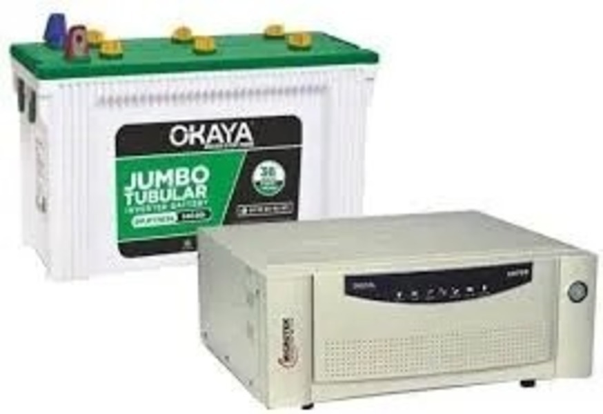
A reliable Okaya inverter setup starts with a measured load schedule, a correctly matched battery bank and a safe separation between mains and backup circuits. By the end, you will know how to prepare a Nagpur site, check the wiring, commission the system and run a backup test that records real performance instead of relying on the nameplate.
Key takeaways
- Record motor starting loads, site voltage and required backup time.
- Match VA capacity, battery voltage and battery quantity to the exact model.
- Test mains failure, load performance and recharge before handover.
- Document readings, battery details and test results for future service.
What to collect before choosing an Okaya inverter
Do not approve an Okaya inverter recommendation from the appliance list alone. A technician must record the site’s electrical conditions, required backup performance and the battery arrangement that the exact model permits. An okaya inverter setup fails early when the quoted VA rating ignores motor starting current or the battery bank uses mismatched units.
Record these details before selecting equipment:
- Connected load in watts and VA, power factor, motor or compressor starting surge, and the circuits that must remain live.
- Desired backup duration, expected operating load during an outage, and whether the system serves a home, shop, office, plant or lift.
- Supply type, phase arrangement, input voltage, frequency, existing distribution-board layout and available changeover or isolator position.
- Exact Okaya model number, inverter topology, rated output, charger rating, permitted battery chemistry and required battery-bank voltage.
- Battery Ah rating, make, model, age, open-circuit voltage, terminal condition and approximate state of health; record charging voltage and current for an existing bank.
- Installation inclusions, warranty-start condition, commissioning report, service escalation route and whether cables, battery stands, protection and earthing are included.
Use the model’s specified DC voltage, not a preferred configuration:
| Battery-bank voltage | Required arrangement | Record before approval |
|---|---|---|
| 12 V | One 12 V battery | Ah rating and condition |
| 24 V | Two matched 12 V batteries in series | Same make, model, age and health |
| 48 V | Four matched 12 V batteries in series | Equal capacity and state of charge |
Never combine old and new batteries in one series string.
How to match inverter capacity, batteries and connected loads
Choose inverter capacity from the connected load, not the brand label. Add the running watts of every device that may operate together, then divide by the combined power factor: required VA = watts ÷ power factor. Select an inverter above that result and verify its surge rating for pumps, motors, refrigerators or lifts.
1. Record both watts and VA for each load. A 500 W load at 0.8 power factor needs 625 VA. Add starting demand separately; an inverter that handles running watts but not motor surge will trip during startup.
2. Match the battery bank voltage to the exact model specification. A 12 V inverter takes one 12 V battery; a 24 V system uses two matched 12 V batteries in series, and a 48 V system uses four. Series connection raises voltage, not Ah.
Parallel strings raise Ah, but every battery must match in make, model, age and condition.
3. Estimate battery size with Ah = required AC watts × hours ÷ (battery volts × usable discharge × inverter efficiency). For two 12 V, 150 Ah batteries, nominal energy is 3,600 Wh; at 80% usable discharge and 85% efficiency, usable AC energy is about 2,448 Wh, giving roughly 4.9 hours at 500 W.
4. During the Okaya inverter setup, confirm the battery chemistry, charging voltage and current limit. Tubular, VRLA/SMF and lithium batteries require different settings.
The Okaya inverter installation process should record actual load, battery voltage under load, alarms and shutdown time. Temperature, ageing and Peukert effect reduce the calculated runtime.
The Okaya inverter installation process for a Nagpur site
A sound okaya inverter installation in nagpur starts with the site and distribution board, not the inverter’s VA label. Record the supply phase, load schedule, cable routes, battery location, ventilation, moisture exposure and available earthing point before drilling or wiring.
1. Inspect the distribution board and separate essential circuits—lights, fans, networking equipment and selected refrigerators—from pumps, irons, heaters, air-conditioners and microwave ovens. Note motor starting current and confirm which circuits require backup.
2. Place the inverter on a firm, dry, level surface with the manufacturer’s clearance around vents. Keep batteries upright, accessible and away from heat, sparks, combustible storage and standing water.
3. Install correctly sized DC cables for the battery voltage and expected current. Protect the positive conductor with a suitably rated fuse or DC breaker near the battery, use crimped lugs, observe polarity and secure every termination.
4. Run a continuous protective-earth conductor from the inverter chassis to the designated earthing system. An earth electrode alone does not replace this conductor or a correctly rated protective device; record earth continuity, polarity and insulation results.
5. Connect the AC input and output through rated conductors, secure terminals and a clearly labelled MCB or approved changeover arrangement. Prevent back-feed to the utility supply; never bridge utility and inverter circuits manually.
6. Verify neutral-to-earth voltage and continuity with a meter after wiring. Do not bond them casually at the output, because the correct arrangement depends on inverter topology and the building’s earthing design.
This documented okaya inverter installation process leaves labelled circuits, test readings and the changeover position clear for the person operating the system.
Safety, compatibility and commissioning checks before handover
Before energising an Okaya inverter installation in Nagpur, verify the exact model, battery voltage, chemistry and Ah rating against the manufacturer’s manual. Tubular flooded, VRLA/SMF and lithium batteries require different float voltage, equalisation rules, ventilation and charging-current limits.
1. Record each battery’s open-circuit voltage, terminal condition and polarity. Confirm series and parallel links produce the inverter’s specified DC voltage, then test positive-to-negative and each conductor to earth with an appropriate meter.
2. Set the charger for the installed chemistry and confirm charging voltage and current remain within the battery maker’s limits. A wrong profile can reduce battery life, cause overheating or create a fire risk.
3. Check live, neutral and protective earth at the input and output. Confirm whether the inverter topology switches neutral, passes it through or bonds it; never add a neutral-earth link by assumption.
4. Test continuous earth continuity from chassis to the designated protective-earth system. Fit the specified MCB, fuse or isolator with correctly sized conductors and secure terminations, then verify the changeover cannot back-feed the utility supply.
5. Measure inverter output voltage and frequency under no load and applied load. Test mains failure transfer, alarms, overload response and low-battery shutdown; “it turns on” proves none of these.
6. Record load, charging current, alarm history and every measured value in the commissioning report. An Okaya inverter service in Nagpur should leave you with this report, warranty-start condition and an escalation contact before handover.
How to run and document a real backup test in Nagpur
Begin with a no-load test after recording the battery open-circuit voltage, terminal condition, battery-room temperature, inverter output voltage and frequency. Measure Nagpur’s actual temperature; lead-acid capacity is referenced near 25 °C, and sustained heat reduces service life and real backup.
1. Open the mains input with the inverter charged. Record the mains-failure transfer time if measurable, output voltage, frequency, alarm indication and alarm-history entry. Confirm that only labelled backup circuits remain energised.
2. Repeat the test with representative essential loads, recording start time, load in watts or VA, battery voltage under load, alarms and transfer behaviour. Do not use a heater unless the inverter, cables and battery bank are rated for its load.
3. Run a controlled test at the customer’s expected operating load. Continue until the specified backup duration is reached or the low-battery warning and shutdown occur; record both points. A unit that merely turns on has not proved runtime or overload performance.
4. Restore mains and record charging voltage, charging current and the time required to return to the agreed state of charge. Investigate abnormal heating, repeated alarms or a battery voltage that fails to recover.
5. Require the okaya inverter supplier in nagpur or okaya inverter service in nagpur to provide the exact model, topology, battery chemistry, Ah and bank voltage, warranty start condition, inclusions, escalation route and signed commissioning report.
Soumya Enterprises should hand over photographs or labels showing AC input, backup output, polarity, isolators, dedicated circuits and final settings.
Related product
 | Inverter Microtek Inverter View product → |
Frequently asked questions
What should you collect before choosing an Okaya inverter?
Record connected appliances, motor starting loads, required backup duration, site voltage conditions and the exact battery arrangement permitted by the model.
How do you match an Okaya inverter to batteries and connected loads?
Compare the inverter’s VA rating and surge capability with running and starting loads, then match battery voltage, quantity and capacity to the model’s specifications.
What does the Okaya inverter installation process involve in Nagpur?
The process includes a site survey, mounting, battery installation, protected wiring, earthing, polarity checks, configuration and a controlled commissioning test.
How do you test and document inverter backup performance?
Record the starting battery voltage, connected load, mains-failure time, inverter output, runtime, low-battery response and recharge result in a signed test record.
Keywords